Overblown Egg Timer, part 3
by TheWatcher on Apr.10, 2020, under General, Hardware
Part 1 covered the overview of what I wanted to achieve, while part 2 covered the construction of the hardware. In this third part I’ll give an overview of the software running on the Arduino to coordinate button presses and lights.
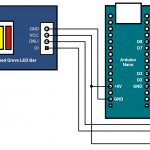
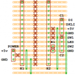
But first, some revised diagrams – in part 2 I found that using the D0 and D1 pins for communication with the Grove LED bar was a poor choice, and had to rework things to use D7 and D8. Here’s how that change looks in glorious technicolour diagram form (click to enbiggen):
The software to support this project splits into roughly four pieces:
- The Arduino sketch (the core code to set up the board, and do something in a loop)
- Some code to control the LED in the illuminated switch button, and to read button presses
- Something to implement the overall behaviour of the system.
- The Grove LED Bar support library, used to control the LED bar
You can find the code for 1, 2, and 3 in this repository in GitHub. I also had to make a few changes to the Grove LED Bar library, and you can find that in this repository, also on GitHub. I won’t delve into the code here in any detail – there’s a lot of documentation in the code, and if you’re interested that will hopefully be sufficient to explain what’s going on in there – other than to note the correspondence between the above-noted code parts and the files in the repository that implement those parts:
- laundry.ino is the arduino sketch file. This contains the setup code, and the loop() function that fetches events from the switch control code, and passes them to the FSM.
- SwitchControl.h and SwitchControl.cpp contain the definition and implementation of a C++ class that handles communication with the push button switch and its illumination LED.
- FSM.h and FSM.cpp contain the ‘brains’ of the project, the Finite-State Machine and the implementation of the various states the system can be in.
If you know what a Finite-State Machine is, you can probably skip most of the rest of this post – don’t worry, there won’t be a test later – but otherwise…. What is a Finite-State Machine? Well, to put it in an almost-Wikipedially less-than-helpful way, it’s a machine that can be in one of a finite number of states at any given time:
- The FSM knows which states are valid states, usually by keeping a list of the valid states in some form, and for each state it knows which other state or states it can move to.
- The FSM knows which state it is currently in.
- There’s some way to tell the FSM to move from one state to another; this can be as a result of internal events within a given state, or an external event that causes a shift from one state to another. Some FSM implementations make this internal/external distinction very explicit, others do not.
In our everyday lives, we’re surrounded by FSMs of various kinds and complexities. A simple example is a timed traffic light, where the lights cycle without external influence:
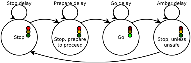
There are four states ((for a UK/EU light; patterns are different in other places)):
- “Stop”
- “Stop, prepare to proceed”
- “Go”
- “Stop, unless unsafe” ((Also known as the “put your foot down to make it past the light before it goes red” state)).
These are the valid states the state machine can be be in ((Okay, there’s a fifth state that can happen: the ‘off’ state when the power is off for some reason, but we’ll ignore that in this example for simplicity)), and each of the lines with arrows shows the possible states any given state can move to:
- The machine can either stay in the “Stop” state, or it can move to the “Stop, prepare to proceed” state.
- The machine can either stay in the “Stop, prepare to proceed” state or move to the “Go” state
- … and so on.
In the case of a timed traffic light, the lights start off in one state – for the sake of argument, say it starts in the “Stop” state – and remain in that state for some period of time ((which generally feels far longer than any of the other directions are stopped for)). Once the ‘stop delay’ time has passed, the light moves to the “Stop, prepare to proceed” state, where it remains for another delay period before moving to the “Go” state, and so on. In this case, all the transitions are the result of internal events – timers control how long the machine stays in one state before moving to the next – and there are no complex decisions about which state to move to next. Thankfully, the FSM for this project is only a bit more complicated:
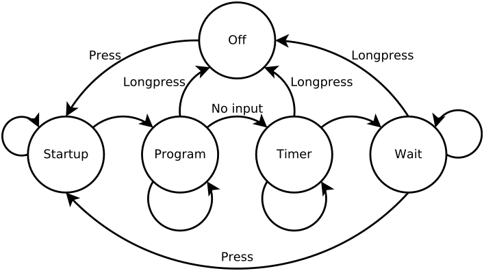
There are five states the machine can be in, with “Off” being an explicit state this time. This FSM also adds external events as a way of triggering state changes: input from the user in the form of button presses can move the machine from one state to another (for example, in every state holding down the button for more than the ‘long press’ time moves the machine to the “Off” state) , in addition to internal events like the LED bar filling up or timeout periods triggering state changes.
The five possible states are:
- “Off”. In this state, the LEDs are all off, and all that happens is that the program checks to see whether the button has been pressed to turn the timer on. This would probably be better named “Standby”, but I’ve made the diagram and named things in the code, and
I’m too lazy toI might introduce errors if I change it all now. - “Startup” is where the button LED is turned on, and the bar fills up as a sort of self-test to show everything is working. The machine stays in this state until the bar is filled, and then it moves to the “Program” state.
- “Program” is the state where the user programs the time the timer should count up to; each press of the button adds a bar to the display, and each bar is worth 1800 seconds (30 minutes). If the user doesn’t press the button for over 2 seconds, the selected bars flash on and off a few times, and after 4.5 seconds of inactivity the time is set and the machine moves to the “Timer” state.
- In the “Timer” state, the bar lights up one LED after another as the programmed time passes. Once the bar is completely lit (i.e.: the programmed time has elapsed), the machine moves to the “Wait” state.
- In the “Wait” state, the LEDs in the bar are lit up in a ‘chase’ effect, where one fully lit LED moves back and forth on the bar, with a ‘trail’ of decreasing brightness LEDs behind it. The machine remains in this state until the user presses the button, at which point the machine moves back to the “Startup” state.
Some of these states – 3 in particular – are arguably compound states, as there are different things happening within the same state. For example, in the case of the “Program” state there is a distinction between the behaviour up to 2 seconds of inactivity, and between 2 and 4.5 seconds, but keeping both behaviours in one state made the overall implementation of the system less complex. This highlights one of the problems with building finite-state machines: the breakdown of a system’s behaviour into states is not always obvious or straightforward: sometimes combining states can make implementation easier, while sometimes it can be counterproductive, and often the result is a compromise informed by experimentation and experience.
All the state definitions and implementations for the project’s FSM are in the FSM.h and FSM.cpp files in the repository, and the design was chosen to make it easy for me to add additional states if needed, or modify an individual state without affecting the overall machine in any way. Each state keeps all the information it needs to operate within its own variables, as much as possible. A significant departure from this can be found in the “Program” and “Timer” states: the user sets a time in the “Program” state, and that time has to be passed to the “Timer” state, but the FSM itself doesn’t offer any clean way to transfer data between states.
Data transfer between states is a subject that causes a modicum of disagreement online ((see also: rage-filled screaming arguments)), and a wide variety of potential methods exist. All are typically considered to be terrible and no better than any others. In the end, I decided that the most straightforward approach was to have a shared variable, and the “Program” state can write the selected time into it, and the “Timer” state can read from it – in a multithreaded or otherwise more complex system, this would be fraught with potential dangers, but in the simple, single-threaded environment of an Arduino, there’s no scope for serious problems there.
At this point, the hardware works, and the software works – next up, I need a box to put it all in. That’ll be the subject of part 4.
You must be logged in to post a comment.