Adventures with Arduino (pt 2)
by TheWatcher on Mar.25, 2020, under General, Hardware
In part 1 I outlined the general – if crazy – idea I intend to attempt. In this part, I’m getting down to actual hardware – starting with the switch and illumination LED I left off at in part 1.
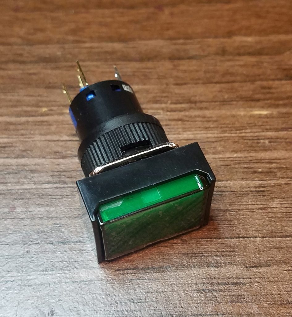
The switch I ended up buying was a RJS-K16-291-GE-65J , a momentary push-button switch with a green illuminated button that is lit up using a LED set up for use with a 12V supply. This is, as previously noted, less than ideal for use with the 5V supply used by the Arduino Nano – so the first thing to do is take the switch apart to see how easy it might be to replace the resistor or the LED assembly with something more suitable.
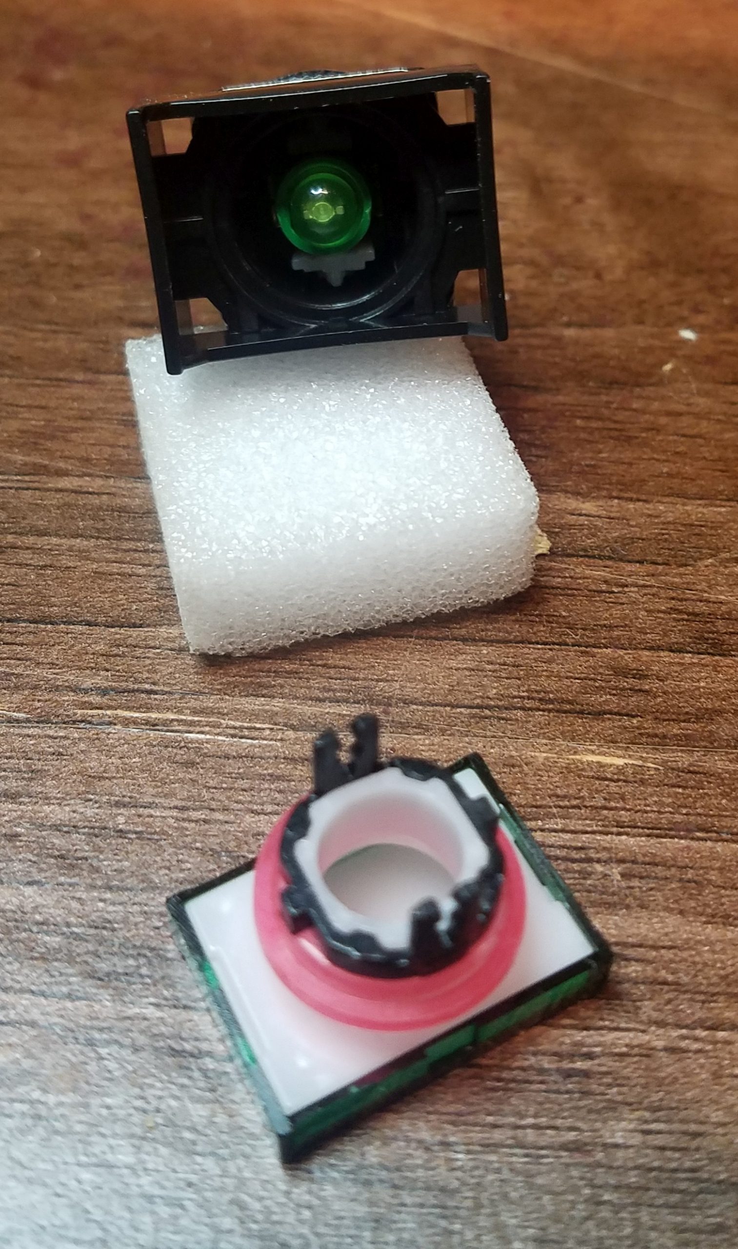
The datasheet for the switch isn’t entirely helpful about how the switch goes together, so I approached the problem by the tried and true method of pulling on bits until something gives. Thankfully, the green button actuator pulls off to reveal the LED module behind it.

Less helpfully, the LED module has the resistor built-in, and it is a pretty-much sealed unit – this is the little green module at the bottom of the picture to the left. I couldn’t work out a way to get inside without irreparably damaging it, so I decided it’d be best to just replace the whole thing, and solder the current limiting resistor to the contact on the back of the switch rather than inside it.
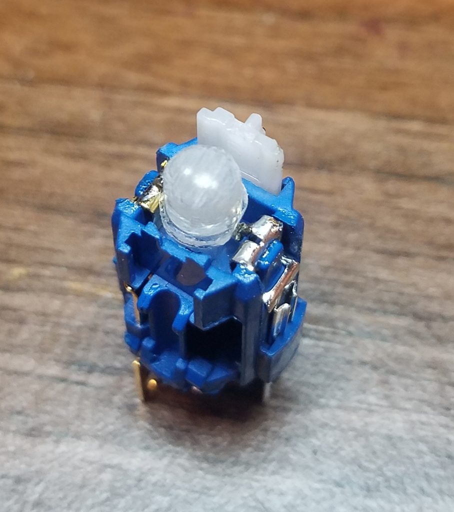
In my pile of it-might-come-in-handy-some-day parts I have a number of LEDs I could use as a replacement, but they are all conventional hemisphere 5mm LEDs with narrow viewing angles, rather than the much wider viewing angle afforded by the stubby ‘straw-hat’ style LED supplied with the switch. There is a way to deal with this problem, of course: bloody-mindedness and brute force! After hacksawing the top off the 5mm LED to remove the lensing effect of the epoxy dome, and then thoroughly sandpaper the rest of the housing to maximise the diffusion, the resulting abomination was a passable imitation of something that would do the job.
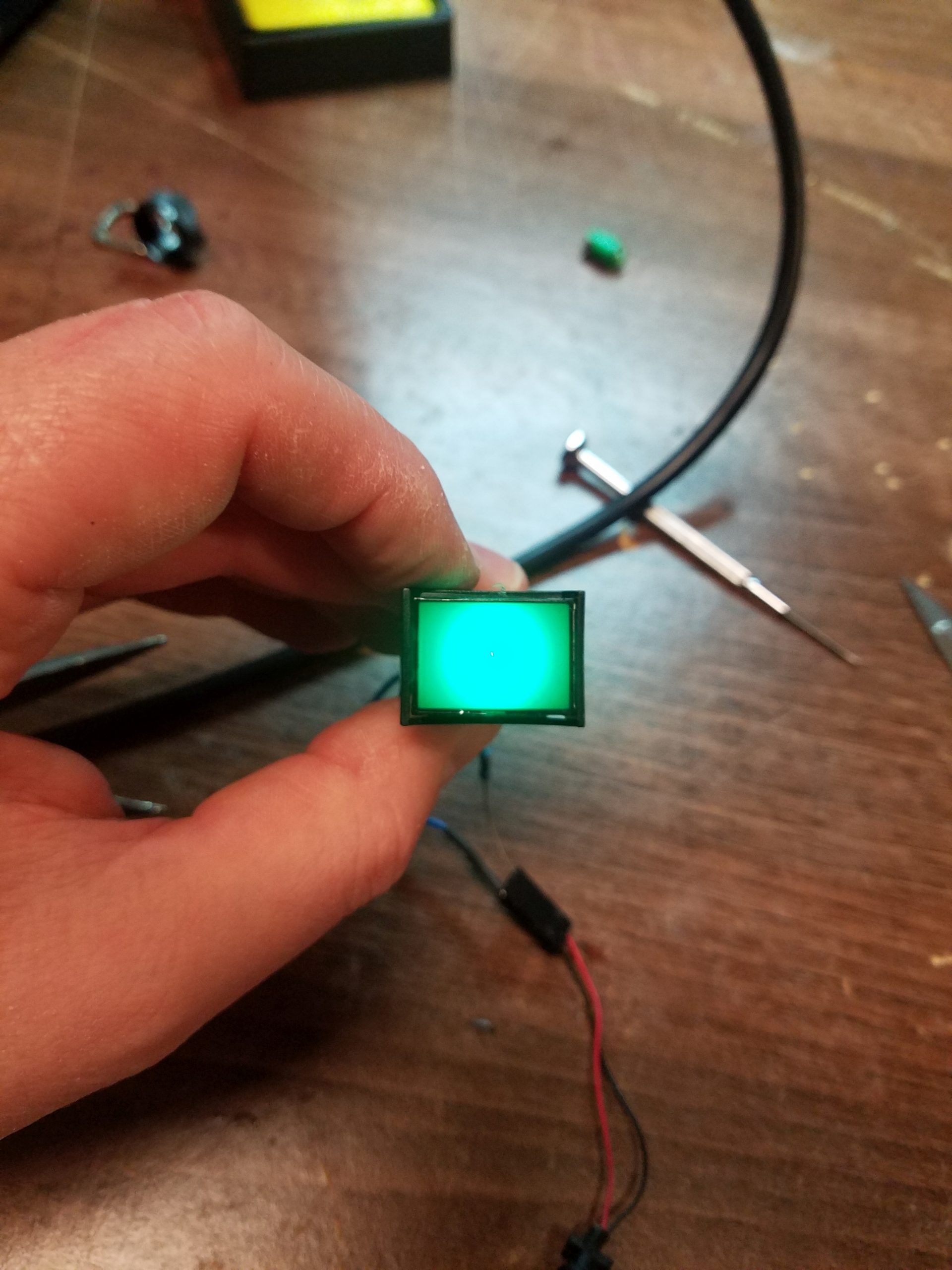
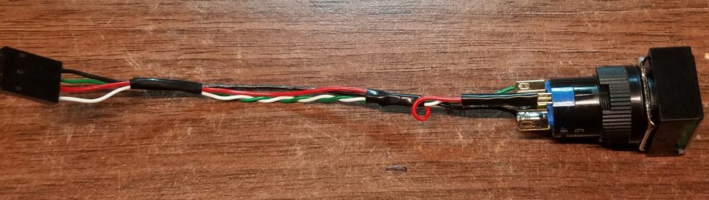
The FrankenLED soldered into place in the switch body 
Eh, it’ll be reet.

The last thing to do with the switch is to add the cables and a 4-pin M20 connector to plug into a header on the board I needed to make that would allow me to more safely connect everything to the Arduino.
The next step was to fix the connector supplied with the Grove LED Bar. The seeed Grove system assumes you will be using one of their shields to connect modules using separate 4 pin JST-PH connectors, whereas I am building my own board and will just use another 4-pin M20 for the LED Bar.
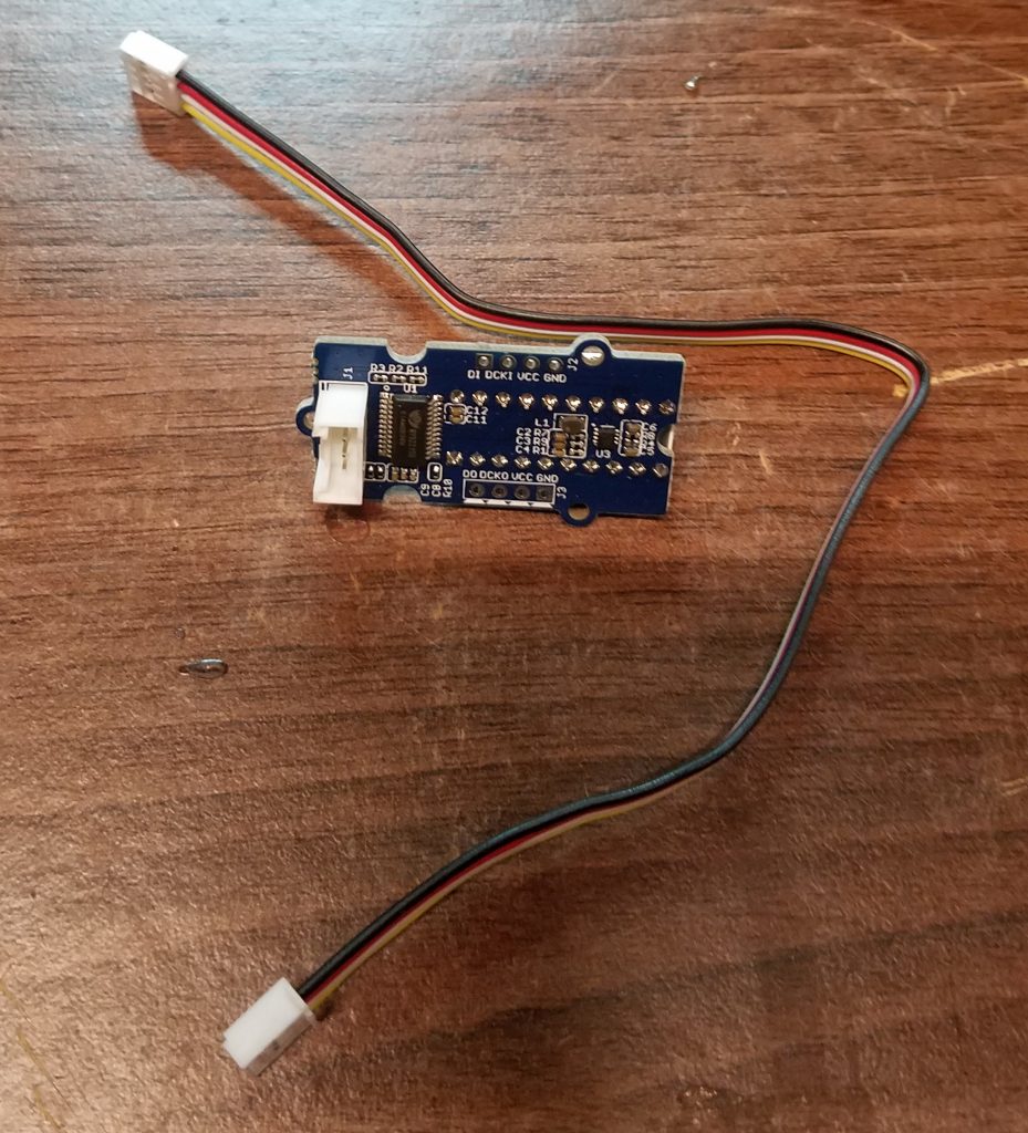
From this… 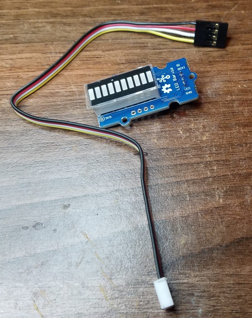
… to this
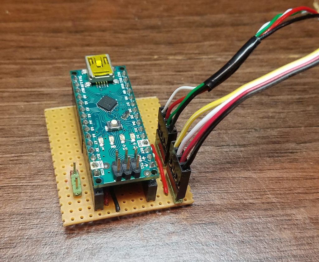
The board itself is fairly strightforward: a pair of headers for the Arduino to plug into, three sets of pins for the connectors (one for power, one for the LED bar, and one for the switch), some wires to route power around, and one pulldown resistor to drive the data pin for the switch low when the switch is not pressed.
It all seemed to go together fine, and initial testing of the switch part was flawless. However, it appears that I made something of an error in my selection of data pins 0 and 1 for the lines to drive the Grove LED Bar. While it made for a nicer board, it meant that things went ‘sproing’ a bit (it’s a technical term) when trying to program the Arduino and test the LED bar itself.
So, back to the drawing board soldering iron I went and added in a new set of pins and some more wires to take the power to the LED bar connector. Now the LED bar signal and clock are provided by D7 and D8 instead. It’s not as clean as I’d have liked it, but it does work – which after all is the important bit here.
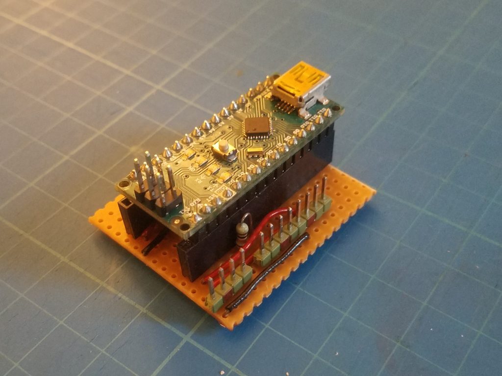
Not my best work, but it’ll do. 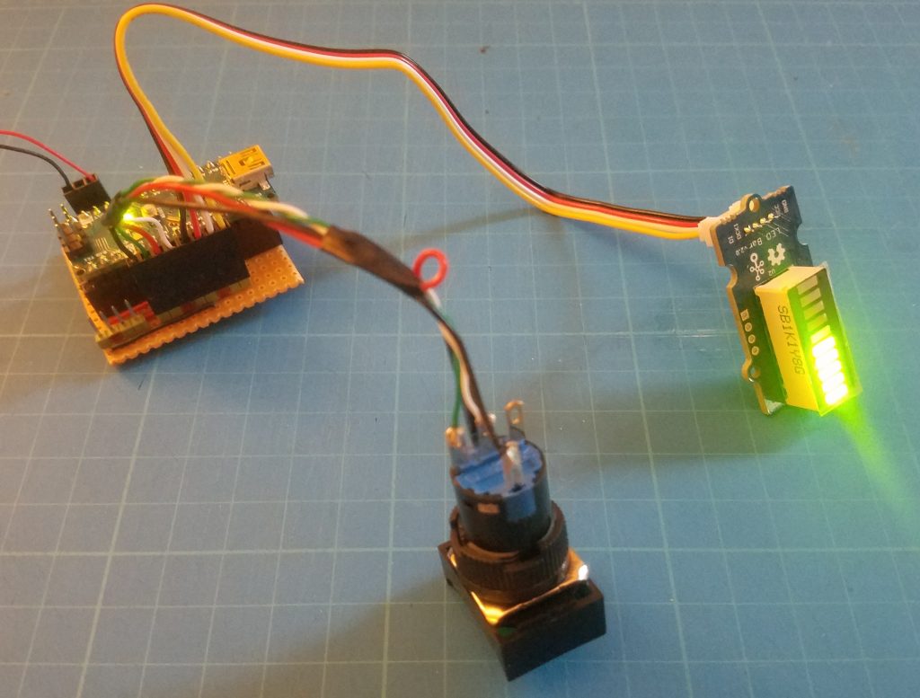
It works, and not a single demon unleashed upon the unsuspecting world!
And that’s the easy part done – now comes the software to drive it. But that’s for part 3.
You must be logged in to post a comment.